Visual Inspection
The visual inspection is the first step in any investigation. A properly executed survey consists of a rigorous logging of every defect seen on the concrete surface. The aim of the visual survey is to give a first indication of what is wrong and how extensive the damage is. If concrete is spalling off, then that can be used as a measure of extent of damage. In some cases, weighing the amount of spalled concrete with time can be a direct measure.
The main equipment is obviously the human eye and brain, aided with a notebook, proforma or hand held computer and a camera to record and locate defects. Binoculars may be necessary, but close inspection is preferred if access can be arranged. A systematic visual survey will be planned in advance. Many companies that carry out condition surveys have standardised systems for indicating the nature and extent of defects. These are used in conjunction with customised proformas for each element or face of the structure. It is normal to record date, time and weather conditions when doing the survey and to note visual observations, such as water or salt run down, damp areas etc.
Interpretation is usually based on the knowledge and experience of the engineer or technician conducting the survey. The main limitation of visual inspection is the skill of the inspector. Some defects can be mistaken for others. When corrosion is suspected, it must be understood that rust staining can come from iron bearing aggregates rather than from corroding reinforcing steel. Different types of cracking can be attributed to different causes Visual surveys must always be followed up by testing to confirm the source and cause of deterioration
There is far more detail on these and other techniques in the latest edition of my book. Details for ordering are on the home page of the website.
Delamination Surveys
As corrosion proceeds the corrosion product formed takes up a larger volume than the steel consumed, building up tensile stresses around the rebars. A layer of corroding rebars will often cause a planar fracture at rebar depth prior to spalling of the concrete. The aim of a delamination survey is to measure the amount of cracking between the rebars before it becomes apparent at the surface. It should be noted that this can be a very dynamic situation.
The delamination survey with a hammer is often conducted alongside the visual survey with hollow sounding areas marked directly onto the surface of the structure with a suitable permanent or temporary marker and then recorded on the visual survey pro forma. The hammer or chain drag survey is usually quicker, cheaper and more accurate than alternatives such as radar, ultrasonics or infrared thermography. The other techniques do have their uses, e.g. in large scale surveys of bridge decks (ultrasonics and infrared), or waterproofing membranes or other concrete defects (ultrasonics and radar). The reader is recommended to review the literature for further information.
For interpretation, the experience of the inspector is vital. A skilled, experienced technician will often produce better results than the more qualified but less experienced engineer. Trapped water within cracks, deep cracks (where bars are deep within the structure) and heavy traffic noise can complicate the accurate measurement of delamination.
It is common during concrete repairs for the amount of delamination to be far more extensive than delamination surveys indicate, because of the inaccuracy of the techniques available and also because of the time between survey and repair. Once corrosion has started, delaminations can initiate and grow rapidly. An underestimate of 40% or more is not unusual and should be borne in mind when budgeting for repairs.
Carbonation Depth
There are two principal causes of corrosion. They are chloride contamination and carbonation of the concrete. Any survey must distinguish between the two. The distinction is important because the type of repair may be determined by the cause of corrosion. The neutralisation of the pore solution by the carbonation process leads to a "carbonation front", where there is a transition from around pH 12 to pH 8.
Carbonation is easily measured by exposing fresh concrete and spraying with phenolphthalein indicator solution. The measurement can be done either by breaking away a fresh surface (e.g. between the cluster of drill holes used for chloride drilling), or by coring and splitting, or cutting the core in the laboratory. The phenolphthalein solution remains clear where concrete is carbonated and turns pink where concrete is still alkaline. The best indicator solution for maximum contrast of the pink coloration is a solution of phenolphthalein in alcohol and water. If the concrete is very dry then a light misting with water prior to applying the phenolphthalein will also help show the color. Petrographic analysis will also reveal carbonated and partially carbonated zones under an optical microscope.
Sampling can allow the average and standard deviation of the carbonation depth to be calculated. If the carbonation depth is compared with the average reinforcement cover, then the amount of depassivated steel can be estimated. If the carbonation rate can be determined from historical data and laboratory testing then the progression of depassivation with time can be calculated.
In some aggregates accurate phenolphthalein readings are difficult to obtain. Some concrete mixes are dark in colour and colour change may not be visible. Care must be taken that no contamination of the surface occurs from dust and the phenolphthalein sprayed surface must be freshly exposed or it may be carbonated before testing. High alumina cement (HAC) concrete does not show the colour change well although HAC concretes may be highly susceptible to carbonation because of low alkali content.
It is also possible for the phenolphthalein to bleach at very high pH, e.g. after electrochemical chloride extraction or realkalization. If the sample is left for a few hours, it will turn pink. There can also be problems on buried structures where carbonation by ground water does not always produce the clear carbonation front induced by atmospheric carbon dioxide ingress. Also phenolphthalein changes color at pH 9.5 while concrete starts to corrode below pH 11. This could be important in realkalized concrete, where the pH may not reach 11, but may reach 9.5.
Chloride Content
Chlorides can be cast into concrete or can be transported in from the environment. The chloride ion attacks the passive layer even though there is no significant drop in pH. Chlorides act as catalysts to corrosion. They are not consumed in the process, but help to break down the passive layer of oxide on the steel and allow the corrosion process to proceed quickly. Chloride contents are measured by sampling the concrete and analysing a liquid extracted from the sample. This is usually done by mixing acid with concrete dust from drillings or crushed core samples. An alternative is pore water extraction by squeezing samples of concrete or, more usually, mortar. This technique is frequently used in laboratory experimental work as it is often difficult to extract useful pore water samples from field concrete. A third technique is to crush concrete and boil it in water to extract water soluble chlorides only.
To measure the chloride profile in the concrete, chloride samples should be collected incrementally from the surface either by taking drillings or sections from cores. The first 5mm is usually discarded as being directly influenced by the immediate environment and then measurements of chloride content made at suitable increments. For improved statistical accuracy, multiple adjacent drillings are made and the depth increments from each drilling are mixed. There are several ways of measuring the chlorides once samples are taken. Field measurements of acid soluble chloride can be made using a chloride specific ion electrode. Conventional titration e.g. by BS 1881 part 124 and potentiometric titration methods are also available.
As well as acid soluble chloride, there are the water soluble chloride tests (ASTM C 1218, American Association of State Highway Officers (AASHTO) Test T 260 and Federal Highway Administration Report FHWA RD-77-85). These techniques use different levels of pulverisation of large samples that are refluxed with water to extract the supposedly unbound chlorides. These chlorides are or can become free in the pore water to cause corrosion as opposed to the chlorides bound by the aluminates in the concrete, or bound up in some aggregates of marine origin. The water soluble chloride test is rather less accurate than the acid soluble test because some of the "bound" chlorides can be released, and the finer the grinding the more will be extracted. However, this test can be useful in showing the corrosion condition where chlorides have been cast into concrete, and particularly where aggregates are known to contain chlorides that do not leach into the pore water.
The corrosion threshold is usually given as approximately 0.4% chloride by weight of cement, 0.05% chloride by weight of concrete or 1.2 lb/cu. yd. of concrete. This is only an approximation because:
- concrete pH (14 - log10 of the OH- concentration), varies with the cement powder and the concrete mix. A small pH change is a massive change in OH- concentration, and therefore the threshold moves radically with pH;
- chlorides can be bound chemically (by aluminates) and physically (by absorption on the pore walls). This removes them (temporarily or permanently) from the corrosion reaction;
- some aggregates contain chlorides that cannot be leached into the pore water. They do not play any part in the corrosion threshold but will show up on acid soluble chloride tests.
- in very dry concrete, corrosion may not occur even at very high Cl- concentration as the water is missing;
- in saturated concrete corrosion may not occur even at a very high Cl- concentration as the oxygen is missing.
Corrosion can be observed at 0.1% chloride in some cases and none seen above 1.0% chloride by weight of cement or more in others. If d) or e) are the reasons that no corrosion is observed, then a change in conditions may lead to corrosion.
The important questions from chloride measurement are how much of the rebar is depassivated and how will this progress. Points a) to c) above review how the corrosivity of the chloride can change. If chlorides have been transported in from outside, then the chloride profile can be used along with measurements (or estimates) of the diffusion constant to estimate future penetration rates and the build-up of chloride at rebar depth.
In Europe it is normal to quote the chloride content as a percentage by weight of cement. In many cases assumptions must be made about the cement content because the measurement is by weight of sample (concrete), and the true cement content is not known.
Concrete Resistivity Measurements
The four probe resistivity meter is now used for measurement of concrete resistivity on site. The measurement can be used to indicate the possible corrosion activity if steel is depassivated. The electrical resistivity is an indication of the amount of moisture in the pores, and the size and tortuosity of the pore system. Resistivity is strongly affected by concrete quality, i.e. cement content, water/cement ratio, curing and additives used.
The four probe resistivity meter used for soil resistivity measurements has been modified for concrete application and is used by pushing pins directly onto the concrete surface with moisture or gels to enhance the electrical contact. There at least two versions of the equipment. Other variations use drilled in probes or a simpler, less accurate two probe system.
An alternative approach measures the resistivity of the cover concrete by a two electrode method using the reinforcing network as one electrode and a surface probe as the other.
Concrete resistivity of the area around the sensor is obtained by the formula:
Resistivity = 2 . R . D (ohm.cm)
where:
R is the resistance by the "iR drop" from a pulse between the sensor electrode and the rebar network;
D is the electrode diameter of the sensor
The interpretation of resistivity measurements with regard to corrosion is empirical. The following interpretation of resistivity measurements has been cited when referring to depassivated steel.
| > 20 kohm.cm | Low Corrosion rate |
| 10-20 kohm.cm | Low to moderate corrosion rate |
| 5-10 kohm.cm | High corrosion rate |
| <5 kohm.cm | Very High Corrosion rate |
Researchers working with a field linear polarisation device for corrosion rate measurement have conducted laboratory and field research and found the following correlation between resistivity and corrosion rates using the surface to rebar two electrode approach:
| >100kohm.cm | Cannot distinguish between active and passive steel |
| 50-100kohm.cm | Low corrosion rate |
| 10-50kohm.cm | Moderate to high corrosion where steel is active |
| <10kohm.cm | Resistivity is not the controlling parameter |
In this method and interpretation resistivity is used along side linear polarisation measurements (see below).
The resistivity measurement is a useful additional measurement to aid in identifying problem areas or confirming concerns about poor quality concrete. Measurements can only be considered along side other measurements. Reinforcing bars will interfere with resistivity measurements.
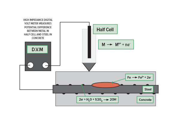
Electrochemical Potential Measurements
Measurement of the electrochemical potential of the steel with respect to a standard reference electrode gives an indication of the corrosion risk of the steel.
The silver/silver chloride (Ag/AgCl) reference electrode is commonly used for steel in concrete. Copper/copper sulphate (CSE) cells are also used but are not recommended because of the maintenance needs, the risk of contamination of the cell, the difficulty of use in all orientations and the leakage of copper sulphate. A high impedance digital voltmeter is used to collect the data in the simplest configuration. Other options are to use a logging voltmeter (or logger attached to a voltmeter), an array of cells with automatic logging or a reference electrode linked to a wheel for rapid data collection.
Interpretation is most reliable for cast in situ, reinforced concrete with chloride induced corrosion due to diffusion of sea or deicing salts. ASTM C-876 states that there is a high risk of corrosion if the potential is more negative than -350mV CSE there is a high risk of corrosion. If the potential is less negative than -200mV there is a low risk of corrosion. In between those values the risk is indeterminate. This interpretation does not necessarily apply to carbonated structures, precast concrete elements or elements with chlorides cast into the concrete. The readings can also be affected by moisture content, with the base of columns or walls showing more negative potentials regardless of corrosion activity. Stray currents can also influence the readings, this can be used as a diagnostic tool where stray current corrosion is suspected in the presence of DC fields.
Very negative potentials have been measured below the water line in marine environments, however, the lack of oxygen will often slow the corrosion rate to negligible levels.
"Junction potentials" can be created by the change in chemical concentrations within the concrete. This effect was severe in a concrete slab subjected to chloride removal, but that may be due to the treatment, rather than being a real problem under normal conditions. Junction potentials may explain the erratic changes in potential seen in carbonated structures. The potential changes across the carbonation front because of the pH change, and because the concentration of dissolved ions changes as carbonated concrete wets and dries quickly because the pores are narrowed by a lining of calcium carbonate.
What we can do for you
- Review the condition of your structure
- Recommend repair options
- Provide designs and performance specifications
- Provide lists of qualified and experienced contractor